| Smoke and Mirrors: Ultra-Rapid-Scan FT-IR
Spectrometry
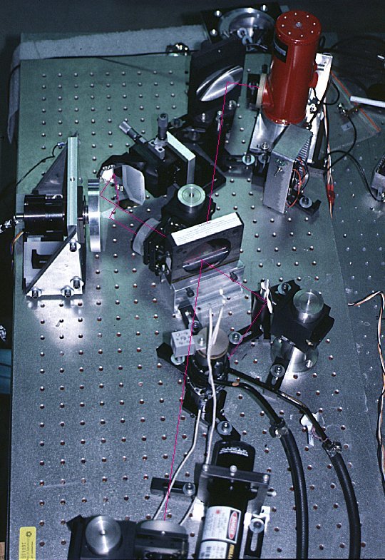
Picture of instrument - This is a picture of the actual instrument which has been constructed on an optical breadboard. The pink line traces out the center of the path of the infrared beam from the source (black tower at center will black hoses for cooling) to the collimating mirror, to the beamsplitter. The fixed arm is formed by the pink line going from the beamsplitter to the mirror at the bottom of the picture. The path through the variable arm requires four reflections from the disk; two going to the fixed flat mirror and two on return. The red dewar at the top of the picture houses the MCT detector. The gray laser detector is just below the MCT and can be identified by the wires hanging out the back. One of the interesting features of this instrument is that the retardation range can be varied without affecting the duty cycle efficiency. This is done by shifting the spinning mirror back and forth such that the beams intercept portions which have different net displacement with rotation. Another method for very conveniently varying the retardation is to adjust the rotation phase between spinning disks in each arm of the interferometer. |